Technology - Interfaces

CALL 1-800-667-7492

T: 1-800-667-7492
Interfaces
Synchronous Serial Interface (SSI)
Rotary Sensors with SSI Interface


Linear Transducers with SSI Interface:


The synchronous serial interface is a digital interface for absolute position and rotary measuring systems. It enables position and angular information to be transmitted digitally, absolutely and without bus overhead. As a result, it is especially well-suited for applications in which reliability and signal robustness are required in an industrial environment.
Transmission is synchronous to the request of the controller, and one bit of the position value to be output is transferred with each clock pulse. The clock/data signals are transferred differentially via a RS 422 interface.
Data formats are binary or Gray-encoded with a 24 or 25-bit position resolution. A parity bit for increased data security can also be attached to the data format ("SSI26"). Possible clocking frequencies are in the range from 60 kHz to 2 MHz, and update rates of up to 16 kHz can be achieved.
The maximum achievable clocking frequency is dependent on the cable length and the driver blocks used. This makes the SSI interface reliable, dynamic and inexpensive.
CANopen Interface
Linear Sensors with CANopen Interface


CANopen is an internationally standardized bus protocol based on the seven-layer ISO/OSI reference model. It was developed by the CIA (CAN-in-Automation user and manufacturer association) and has been standardized as the European standard EN 50325-4 since the end of 2002. CANopen uses layer 1 and 2 of the CAN standard originally developed for use in cars (ISO 11898-2) as a transmission technology.
The bus system enables each device to send messages (multimaster capability). Messages on the bus are received by each bus device (broadcast communication). Each bus device then decides whether or not these messages are processed based on its local intelligence.
A broad range of methods for setting the parameters of bus devices and for error detection and treatment equip the CANopen protocol with outstanding properties.
With reference to position sensors, all relevant device data of the higher-level controller can easily be imported via electronic data sheets (eds files). Thanks to the availability of features like cam switches, limit value switches, speed data etc., a true measured value for connected components is provided here. CANopen is suitable for use as an interface in both dynamic applications and in complex control networks.
Quadrature Interface
Rotary Sensors with Incremental Interface
Linear Sensors with Incremental Interface
The quadrature interface was originally developed for incremental measuring systems.
Here the material measure is applied to a glass pane or strip. This is then scanned with optical systems. Two signals are generated, i.e. an A and a B pulse with a positive or negative phase offset of 90° respectively, depending on the direction of movement. The number of A or B pulses is a measure of the distance covered, and the pulse width of the A/B pulses is therefore dependent on the speed of movement.
In addition, optical systems usually have a reference track, which only outputs a signal once along the entire measuring distance in order to reference the incrementally determined position. This is necessary to derive an absolute position from the A/B pulses which follow.
No reference traverse is necessary for absolute measuring position and rotary sensors as, for example, is the case with magnetostrictive position measuring systems.
A magnetostrictive position measuring system with a quadrature interface transfers the correct number of A/B pulses in accordance with the current absolute position on request.
DyMoS Interface
Like the SSI interface, the DyMoS interface is based on the RS422 standard. With various additions, it combines the simplicity of synchronous serial transmission with the data transmission and diagnostic functions of bus interfaces. Here the data format is 48-bit, which is divided up as follows: the first three bits are system data, followed by 40 data bits and 5 CRC bits. The 40 data bits can be formatted both as position and speed (for a position transducer) and as two position data(with 2 position transducers) with a resolution of 20 bits each.
The system data can be used to monitor the state of the measuring sensor and the CRC bits for monitoring transmission. In addition to the position data, information on the sensor (model and serial number) is output via the DyMoS interface following "Power On" so that the measuring sensor can be clearly assigned in the application. As with the SSI interface, the maximum transfer rate is 16 kHz.
Ethernet / VARAN
In the Ethernet standard IEEE 802.3 data collisions cause irregular delays in data transfer. In order to achieve real-time performance, Industrial Ethernet protocols employ special preventive measures to avoid such collisions.
For hard real-time, signal transmission times must stick exactly to a given time frame, or else they will trigger a failure signal. For soft real-time, some deviation within a limited span of time is tolerable. While cycle times of up to several hundred milliseconds may be good enough for soft real-time applications, e.g. for temperature monitoring, digital control systems or Motion Control applications often require cycle times below one millisecond.
When selecting the right bus system for machine automation, reliability plays a central role in addition to the speed. Based on globally proven Ethernet physics, the hard real-time at the lowest cycle times and maximum data security is provided. Robust, error-tolerant performance in raw industrial environments is also an important performance characteristic of a modern bus system. As a real-time Ethernet bus system, the VARAN bus meets these requirements and offers much more. The company "Sigmatek" has developed in 1994 a real-time bus system for connecting the I / O modules of in that time introduced product series DIAS (DIAS-BUS). VARAN is the evolution of the DIAS bus based on Ethernet.
In the year 2006 the activities relating to disclosure and standardization of the system were transferred to VARAN BUS USER ORGANIZATION (VNO). The VARAN bus is based on standard Ethernet technology. The protocol is implemented completely in the hardware, whereby the burden on the control CPU is reduced.
Instead of standard Ethernet frames, smaller data packets are used with the VARAN bus, guaranteeing the highest possible resistance to disruptions. The immediate repetition of unacknowledged messages within a bus cycle is one of the most important advantages, which characterize the VARAN bus as a future-oriented bus system.
By using the Manager-Client principle, collisions are avoided. The VARAN bus provides highest speed, shortest cycle time and minimum synchronicity jitter. In addition, it offers the unique possibility of asynchronous direct access.
Data packets are repeated within the cycle until a valid acknowledgement is received. Therefore, the validity of all data is guaranteed at the end of each cycle. This permanent testing of data validity, even for bus cycle times less than 100 µs, is only possible through use of the small VARAN data frames (1 – 128 bytes). Due to the flexible network topology, star-, line- and tree topologies can be combined as desired. Another advantage is the easy implementation of existing CANopen® protocols.
The VARAN bus is an open standard and manufacturer-independent.


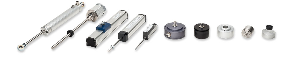
| Rod Type | Touchless | Side Actuated | Rod Type With Return Spring | in-Cylinder | Open Systems |
| Shaft Type | Touchless Rotary | Hollow Shaft | Multi-Turn | Automotive | Open Systems |
| ABOUT | TERMS AND CONDITIONS | PRIVACY |
© 2000-2026 Novotechnik U.S. Inc., All Rights Reserved