|
Engineers specifying a linear position sensor for their product or application have several types of decisions to make. The first is what sensor technology is the best match for my application? The choices are Inductive, magnetostrictive and potentiometric.
Inductive and magnetostrictive are technologies that have a moving position marker that is physically separate from the sensor and is attached to the moving part of your application. In other words these two technologies are touchless. Potentiometric uses a conductive plastic track and wiper that moves along the track as it is connected via a rod to an application's moving part.
For any of the technologies used, one important thing to keep in mind is to select a select a sensor that is a certain margin longer than the travel length you need to measure, but not a lot longer. This will ensure your entire range is measurable and that the best accuracy is achieved.
All technologies used for linear position sensors distinguish between an electrical range and a mechanical range. Novotechnik (and others) use the electrical length when referring to a device. So a 100 mm TE1 Series sensor, for example, would have an
electrical stroke length of 100 mm and a mechanical stroke length of 105 mm. In practical terms, this means the measurable range for this product is 100 mm while its rod moves a distance of 105 mm.
Choosing stroke length for touchless sensors
When using a linear position sensor that is based on touchless technology, many sensors come in different mechanical stroke lengths that can be individually programmed to have electrical stroke lengths that are shorter than specified—strokes by
the factory or—individually—by the customer, without special hardware or software. You just have the electrical length set to your desired length within the limits of the sensor's range and make sure your applications moving part moves 5% to 10% more than that length.
Choosing stroke length for potentiometric sensors
When an engineer specifies a position sensor for their application, there are a few universal aspects that need to be considered to maximize accuracy and avoid pitfalls. Mechanical stroke length, electrical stroke and electrically defined stroke are readily defined and vital to avoid overrun and sensor damage issues while designing in accuracy.
First, it helps to define the terms we are using. Referring to Figure 1, that represents a position sensor track, L1 indicates the defined electrical travel. L2 indicates the continued travel to where the track and bonding material begin to overlap, which becomes a nonlinear connection region as detailed in Figure 2. This is included in electrical stroke length but not defined electrical stroke. L3 indicates the total electrical contact travel of the potentiometer. L4 indicates the mechanical travel.


Requirement 1: total electrical stroke length (L2) should be a minimum of 5%, and preferably 10%, longer than the maximum stroke length your application requires. This ensures overrun errors and damage to the sensor are avoided.
Requirement 2: The closer the defined electrical stroke length can match the application's actual required mechanical stroke length, the larger the change in signal will be over the range of motion. This will give you the maximum signal to noise ratio. If you try and match a small mechanical stroke length to a large electrical stroke, the output voltage change of the signal (or current change) would likely be very small and result in large resolution steps when run through a 10- or 12-bit A/D converter. In closed loop applications, this can cause dither of an actuator, imprecise positioning and overruns of the targeted position.
Linear position sensors are available in dozens of stroke lengths in small enough increments for virtually any application. For example, Novotechnik's TLH has 20 different stroke lengths available—for short strokes in 25 or 50 mm steps between models and above 1,000 mm in 250 mm steps.
|


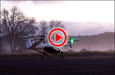
 Just this month NASA began testing of an eVTOL (electric vertical take-off and landing) craft made by Joby Aviation. It is part of NASA's Advanced Air Mobility program to work with advanced technology aircraft to develop a safe air transportation system that according to NASA, "moves people and cargo between places previously not served or underserved by aviation—local, regional, intraregional, urban—using revolutionary new aircraft that are only just now becoming possible." Delivery drones and air taxis fall into the scope of this program too.
