| Choosing the Best Stroke Length for Your Application |
We covered this subject in a past Mechatronics Sense newsletter, though here we have updated this article for newer technology and clarity.
When an engineer specifies a position sensor for their application, there are a few universal aspects that need to be considered to maximize accuracy and avoid pitfalls. Choosing and specifying a mechanical length of travel or stroke length of a position sensor is not enough to avoid problems in many applications. A little more detail is needed.
Note: for a non-contacting, that we refer to as touchless, position sensor using magnetostrictive technology with a floating or track-gliding magnet as well as for inductive technology using a non-magnetic floating or track-gliding marker there are a few different considerations that this article goes into near the end.
Mechanical stroke length, electrical stroke and electrically defined stroke are readily defined and vital to avoid overrun and sensor damage issues while designing-in accuracy. Due to the non-linearities outside a sensor's linearized / defined stroke length a mechanical teach-in (calibration) of two positions is required to obtain highest possible absolute linearity. To get the highest accuracy out of a sensor, it is best done at the 10% stroke and 90% stroke mark.
Potentiometric (track and wiper) linear potentiometers
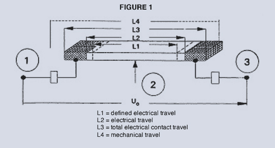
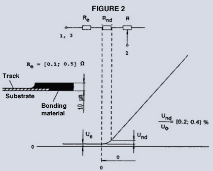
First, it helps to define the terms we are using. Referring to Figure 1, that represents a position sensor track, L1 indicates the defined electrical travel. L2 indicates the continued travel to where the track and bonding material begin to overlap, which becomes a nonlinear connection region as detailed in Figure 2. This is included in electrical stroke length but not defined electrical stroke. L3 indicates the total electrical contact travel of the potentiometer. L4 indicates the mechanical travel. |
 |
 |
Requirement 1: total electrical stroke length (L2) should be a minimum of 5%, and preferably 10%, longer than the maximum stroke length your application requires. This ensures overrun errors and damage to the sensor are avoided.
Requirement 2: The closer the defined electrical stroke length can match the application's actual required mechanical stroke length, the larger the change in signal will be over the range of motion. This will give you the maximum signal to noise ratio. If you try and match a small mechanical stroke length to a large electrical stroke, the output voltage change of the signal (or current change) would likely be very small and result in large resolution steps when run through a 10- or 12-bit A/D converter. In closed loop applications, this can cause dither of an actuator, imprecise positioning and overruns of the targeted position.
Linear position sensors are available in dozens of stroke lengths in small enough increments for virtually any application. For example, Novotechnik's TLH has 20 different stroke lengths available for short strokes in 25 or 50 mm steps between models and above 1,000 mm in 250 mm steps.
Touchless (magnetostrictive or inductive linear position sensors)
Things are even easier with touchless linear position sensors: many of the short and long stroke sensors come in different mechanical stroke lengths that can be individually programmed to—shorter than specified—strokes by the factory or—individually—by the customer, without special hardware or software.
You can re-calibrate the touchless start and end position of a touchless sensor if so required by your controls, but it is usually best and easiest to work with factory calibration, where, for example, with a standard voltage output the 0.1V signal represents "0.0 mm" and 10V output represents "defined total electrical stroke reached."
Touchless sensors by design also have in general a higher tolerance for radial misalignment of the marker towards the sensor housing without causing additional linearity errors.
Mechanical unintentional overruns are not an issue with position markers being guided by the machine movement itself alongside of the sensor housing.
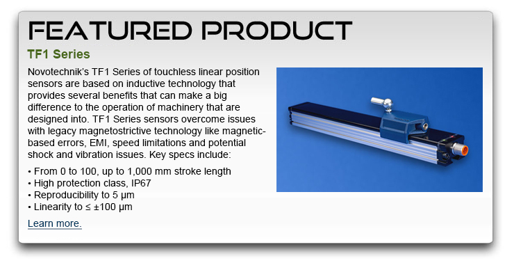
Regarding speed, an application can benefit from inductive linear systems like Novotechniks TF1 that are comparable in speed to potentiometers while also providing an output signal that is virtually free of noise especially with digital outputs like SSI. |
|
|
|


 Actuator Control