 |
|
In this issue:
• 3D volumetric display enables 360°—x, y, z spacial views
• Tech Tip: How Self-Diagnostics for Rotary Sensors Help
• Application: Blood Analyzer
• and more.
Featured video:
https://youtu.be/hrEJg27aQT4
To view newsletter in your browser click here.
|
 |
|
|

3D Volumetric Display Enables Complete Spacial Views of 3D Objects
|
| |
A 3D volumetric display is not 2D reflections on a flat display. It is a genuine 3D projection into 3D space. This means it is viewable from any direction around the complete 360° of the projection and in each dimension—with no special eyewear. To repeat—there is no screen.
It also is not a classic hologram reflecting two-dimensional images.
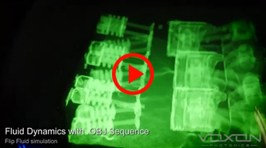
Voxon has created the world's leading 3D Volumetric Display. Here's the technical description from Voxon Photonics. "The VX1 is technically described as a 'swept surface volumetric display' and is powered by the Voxon Photonics Engine. This engine comprises an ultra-high-speed digital projection system (projecting over half a billion points of light every second into physical volumetric space: 500 MVox/s), CPU, volumetric graphics engine and reciprocating light diffuser. Volumetric images are created by projecting slices of light at 4,000 frames per second onto a moving screen, so that they diffuse at precisely the right position in physical space. Through persistence of vision, the human eye blends the slices together, and the result is a true three-dimensional digital object that can be viewed in the same way as one would view a real object, from any angle, and without special goggles or glasses. Users are able to manipulate, and focus on specific areas of any 3D model in intricate detail—with vector files, zooming in right down to the vertex level of the underlying data. The display also supports multi-user interactivity."
VX1's display resolution is 200 million voxels (1,000 x 1,000 x 200). The VX1 including its software supports Blender, Solidworks, Fusion 360, Inventor, RealFlow, Sketchup, 123D Catch, Meshlab and other software generating 3D files including file types: STL, OBJ, DICOM and KV6, 3DS (via POLY2VOX Conversion) and others. Please review Voxon's website for additional formats and support.
So, neat technology but how can it benefit engineers developing and manufacturing products? By being able to have this level of vision during the design and/or manufacturing stages, potential costly issues could be found early avoiding huge costs and product introduction delays down the road. An individual engineer may see something his two-dimensional screen could not reveal or several people collaborating on two mating, but separately designed, components can more readily solve problems or see new opportunities. In another situation, if a component is manufactured at by two different organizations and one works and the other is problematic, the Voxon VX1 could be a powerful tool in getting all stake holders to rapidly get on the same smooth-running page.
This technology already has full support for the DICOM format, used in medical imaging, and Voxon would like to explore the use of CT imaging for industrial use cases where it could aid in the visualization of internal defects. You can find videos of VX1 demonstrating use of DICOM files and other interesting applications on Voxon's web page focused on case studies.
(Source: Voxon Photonics: https://voxon.co)
See the video: https://youtu.be/hrEJg27aQT4
|
|
|

|
| How Self-Diagnostics Assist In Touchless Rotary Sensor Use |
 |
By Ivan Masek, President & CEO, Novotechnik U.S., Inc.
1. Scope
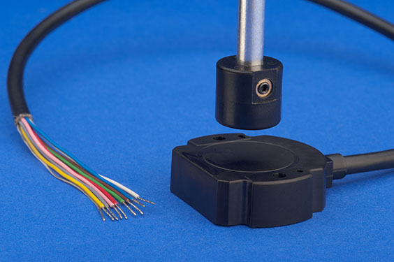
Non-contact rotary position sensors with independent magnet markers have great advantages over their shafted cousins. Mechanical wear, the necessity to seal moving shafts or use additional shaft couplings are a thing of the past. Reduced cost at higher reliability levels is the benefit.
However, the design responsibility to properly align the magnetic marker with the sensor for best possible function is now with the customer. Luckily, it is not rocket science.
Novotechnik supports their customers by providing all information about magnet mounting options (see article in Mechatronics Sense; Spring, 2017). As an aside, Novotechnik offers customers an electronic option, free of charge, to validate the proper function after mounting the sensor beyond reading the correct output signal.
Some rotary sensors, also often referred to as angle sensors, including Novotechnik's RFC 4850 Series, are available with a sensor diagnostics feature. Models can be ordered with diagnostics turned on or off. This article describes what the diagnostics do and offers recommendations on when and how to use them.
The main consideration of a sensor diagnostics system is safety. Users may want to determine whether the rotary sensor will need diagnostics or not. In cases where the sensor will be used in a safety critical function, sensor diagnostics are definitely required. Some of the relevant standards for reference are ISO 13849 and EN280-2013.
In cases where these safety standards are not relevant, the diagnostics still can be very useful. Users can benefit from being able to detect broken sensor wires and the loss of the magnet marker function.
Because of my familiarity with it, I will use Novotechnik's RFC48 Series as an example to go through touchless rotary sensor diagnostic functions and operation.
2. Analog Output Options with Diagnostics
There are 4 analog output options of the RFC48 Series that are available with diagnostics:
- Ratiometric voltage output 0.5 to 4.5 V or 0.25 to 4.75 V output. (Ratiometric in this context means that small variations on the supply voltage side will change the output voltage proportionally.)
- Industrial standard voltage output: Absolute output 0.1...10V (independent of specified variations of supply voltage)
- Mobile standard voltage output: Absolute output 0.5 to 4.5 V or 0.25 to 4.75 V (independent of specified variations of supply voltage)
- Current output 4 to 20 mA (independent of specified variations of supply voltage)
The diagnostic functions available for these output options are the same, however, the diagnostics "watchdog" output types differ. Ratiometric versions of the RFC4850 sensor types use percentages of supply voltage, the absolute output uses fixed voltages and the current output references specific current levels.
3. Diagnostics Turned Off
The RFC4850 series sensor—without diagnostics turned on—will work well outside the defined distance range of the magnetic marker under normal conditions, e.g. in the lab. In fact, the sensor might work in distances as far as twice the recommended distance and one may wonder, "why this is not specified?"
The reason is that the ranges are limited to secure long-term stability and to withstand extreme temperatures, while working flawlessly. Shaft bearing tolerances on the customers' machine may increase mechanical play, further reducing the magnetic field strength as the magnet distance increases. Angular precision, signal stability and noise levels cannot be guaranteed when the magnet is out of the specified range.
4. Diagnostics Turned On
All three analog-output versions of the RFC48 Series have a clearly defined operating output range that does not reach down to a zero output level. Output levels during operation within the defined range state that everything is working fine. A part of this range below the minimum output is defined as the Diagnostics Range. If the sensor system detects an error the output signal will switch immediately into this range:
- Ratiometric voltage output: below 2% of supply voltage
- Absolute voltage output industrial standard: below 20 mV
- Absolute voltage output mobile electronics standard: below 100 mV
- Absolute current output: below 3.5 mA
5. Diagnostics Triggers
Extremely rare internal sensor chip errors due to malfunction of components of the circuitry can activate the diagnostics.
The Hall-effect sensor system designed into the RFC 48 Series functions solely on the orientation of the magnetic field of the magnetic marker mounted to the user's rotary application. This way, the specified function is guaranteed within a wide range of the magnetic field strength which the permanent magnetic marker transmits to the sensor.
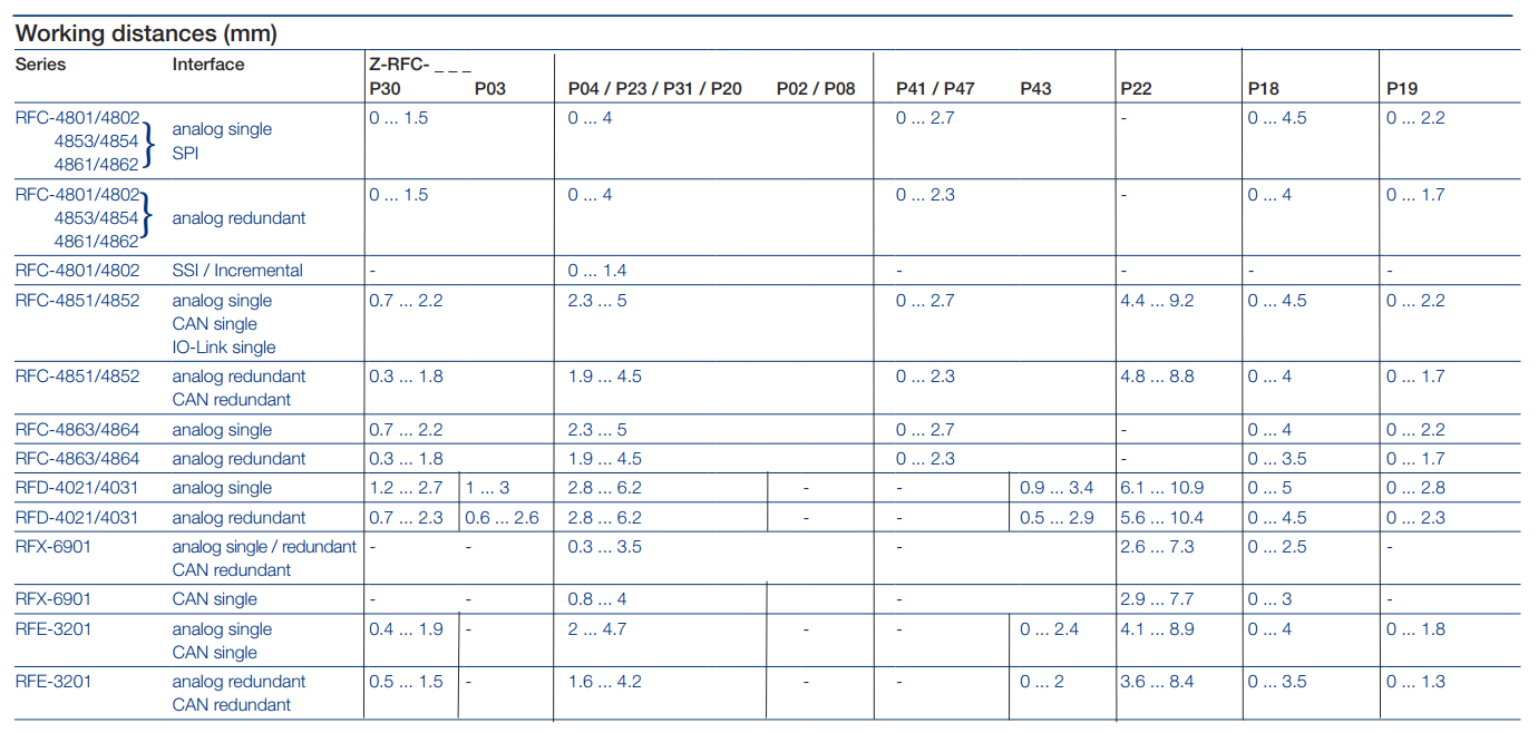
For ease of mechanical integration, the Novotechnik magnetic markers come with a defined distance range instead of complicated magnetic field strength specifications. There is a chart showing the recommended distance range for each of the standard magnets available for the RFC 48 Series. Smaller magnet markers usually provide better performance in smaller distance ranges than larger magnets.
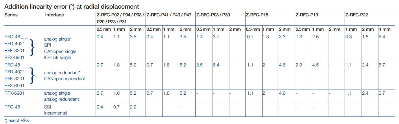
Activated diagnostics limit the sensor to work within the specified magnetic field range. If the magnetic field is too low for safe function, the diagnostics will switch the signal into the previously described diagnostics range. The personnel will notice that the output is in the diagnostics range. The magnet distance can be corrected and once in the correct range, the sensor will immediately display a value in the valid range. This prevents the magnet marker from being mounted in the application at an incorrect distance, avoiding a failure much later under potentially adverse condition.
The magnet markers are well protected against loss of magnetic field strength. Should for whatever reason the distance in the application change or external forces like rocks or gravel destroy the sensor magnet, the sensor output will jump to the diagnostics level. Likewise, if the screws of either sensor or magnet marker were not tightened correctly causing loose components, the diagnostic level output will be triggered.
6. When to Use the Diagnostics
The diagnostics are useful if the System Integrator wants to add another level of safety during integration of the sensor in an actuator closed loop application or in a simple angle display function. The diagnostics definitely help to increase the system's safety in cases where the jump of the output signal into the diagnostics range is acceptable to the system as it can be then stopped or transferred into a safe mode.
Many applications require only the information that one or more wires are broken or that the signal is lost completely and therefore simply being out of the defined range provides enough information to let the control system switch the machine into a safe mode.
There are other non-safety relevant applications where it is better and acceptable to work with a signal that might be slightly deteriorated, as it still might provide more precise angular position information than required as a minimum, but where the loss of signal would have a more negative impact.
The RFC 48 Series, and some other heavy duty Novotechnik sensors, are also available as fully redundant position sensor systems. These can be programmed with custom output characteristics, e.g. different angles, different output gradients and orientation and also with diagnostics individually turned on or off. The available options can provide common-mode error detection on the control system side and also simple watchdog options by way of both sensors providing output signal and only one jumping into diagnostics mode in case of a detected error.
Digital SSI, IO-link, J1939 and CANopen—versions of these sensors are of course also available with diagnostics, some even with more distinguishing options. We will discuss these versions in a separate article in an upcoming Mechatronics Sense edition. |
|
|
|
 Blood Analyzer Blood Analyzer |
|

|
Hemotology diagnostic instruments, also referred to as blood analyzers, require very accurate blood flow for correct measurements. Blood is comprised of plasma and blood cells (red and white). Blood cell count, type, blood type, pH, volume, clotting time and abnormalities as well as hundreds of other test are done by blood analyzers. Measurements have to be accurate and repeatable to ensure reliable results.
An SP 2800 Series rotary sensor, selected by a blood analyzer's manufacturer, measures the position of a valve regulating the flow of blood into a measurement chamber. For viscosity, circulation time and other critical measurements, flow rate is important. Click here for more information on the SP 2800 Series sensor product used in this application.
|
|
|
 |
|
Please email suggestions for technical subjects you would like to suggest for this newsletter to this link: Newsletter Editor
|
|