|
In this issue: Featured videos: To view newsletter in your browser click here. |
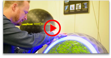 |
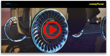
| Watch Goodyear's Technical Concept Video |
|
Take a peek behind the scenes at Goodyear’s innovation process for a duel-purpose ‘tire’ to be used in a new kind of vehicle application and meet, as they put it, “future mobility challenges”. It’s a process that blends mechanical, electro-magnetic, aeronautical, industrial design and materials science knowledge with rubber. They call the result the Aero and it’s designed for what the Goodyear designers and scientists on their innovation team see as an approaching future need. |
| Getting the benefits of magnetostrictive sensing while avoiding potential down-time issues |
|
|
Once every decade or so, it seems, a new technology emerges that provides real benefits over previous technologies. Magnetostrictive sensing was one such technology. It eliminated the need for a conductive plastic track and metal wiper used in the older technology of potentiometric sensors.
The benefit from magnetostrictive sensors is that there was no contact between the magnetic pickup and the sensor. This eliminates the possibility the track and wiper can wear out causing inaccuracies or complete failure, because there is no track/wiper needed. So machine designers saw longer sensor life with reduced possibility of problems as substantial benefits. But, along with the good benefits, there came some new, and to some extent, hidden problems. One problem is that in many industrial environments, small metal flakes and filings are present around machinery. These flakes are often magnetic and therefore attracted to magnets. When they get attracted by the magnet in the magnetostrictive sensor pickup, they can become trapped between the pickup and sensor and accumulate over time. This can lead to erroneous results or even failure of a sensor that can cause unplanned machine down time. Another environmental concern is electromagnetic interference, referred to as EMI. By nature of its technology, magnetostrictive sensors are susceptible to spurious errors from EMI that are usually present in high-powered machines. As one of the machine designers, if you specify the component layout including line power transformers and other electrical power components, you may be able to mitigate this issue. On the other hand if there are other engineers tasked with the responsibility of the power aspects of the machine they may prioritize other trade-offs higher than your sensor. Other nearby machinery, in a plant your machine is used in, can also cause significant EMI problems that you have no control over at all. Machines that have high power and/or dynamic/moving parts will generate vibration and often shock as well. Sensor specifiers can avoid post-product-release problems in this area by checking sensor specifications for high shock and vibration tolerance.
|
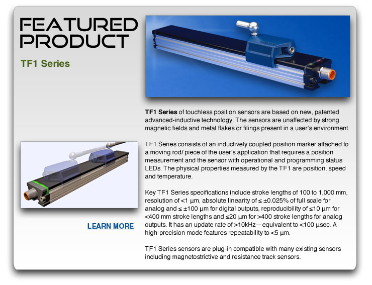
Shock and vibration specifications above 85 g shock and 15 g vibration are are considered good and safe values for almost all industrial and vehicle applications. If you are specifying a magnetostrictive sensor, you would be well advised to check these two specifications.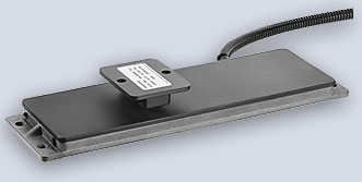 After calling attention to some real and substantial issues, now the good news! A new technology has emerged that does provide all the benefits of magnetostrictive sensors without any of the above short comings. It is called advanced inductive sensor technology. This technology is superior to prior inductive technologies in that it is very accurate and fast. Advanced inductive sensors are inherently immune to metal flakes and filings as there is no magnet to attract them. The pickup works on an inductive principle, not magnetic. This also makes advanced inductive sensors immune to EMI as well. With speed capability to >10kHz (less than100 µsec cycle time), this technology can keep up with virtually any application. And with absolute linearity of ≤ ±0.025%, advanced inductive sensors can deliver all the accuracy needed as well, for all but those that need to measure lengths as tiny as tens of microns. Absolute linearity is the amount of variance from an ideal straight line representing output ÷ input from minimum to maximum. One example: a sensor’s stroke length of 0 to 200 mm is sensed and represented by an output of 0 to 10 VDC. The maximum variation from a straight line of 0 to 10 would be (±0.025% • 200 mm) ÷ 100% = ±0.05 mm. See the Sensor Tip from Mechatronics Sense vol. 1 issue 4 for a primer on calculating total sensor accuracy for an application, found here. |
| Editor’s note: for more information on advanced inductive sensor technology, contact Novotechnik and ask for our white paper on this topic or click here. | |
|
|
|
 Racecar Gear Position Racecar Gear Position |
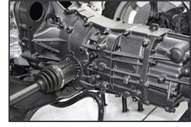 Racing teams need components that have ultra-high reliability and high frequency of use under strenuous conditions. If they have been proven in race conditions it’s even better. Whether it’s the top and most known autosport in the U.S. that begins with “N” or the European one that begins with “F” (apparently even using their names is an askcar and letter-after E1 no, no). Racing teams need components that have ultra-high reliability and high frequency of use under strenuous conditions. If they have been proven in race conditions it’s even better. Whether it’s the top and most known autosport in the U.S. that begins with “N” or the European one that begins with “F” (apparently even using their names is an askcar and letter-after E1 no, no).Changing gears in a race car is a big deal. Controls are usually integrated into the steering wheel so that the driver can make split-second changes and not lose an instant moving hands from steering wheel to a control elsewhere in the cockpit. A rotary position sensor is used to sense the precise angle of a rotating gear-change rod. Top teams chose to rely on the RFC 4800 Series of non-contact angle sensors as it measures gear rod position for control system and provides output for gear position so the transmission can function when it gets input from the driver's controls. It was selected for high tolerance to vibration of up to 20 g, high reliability and long life. It’s inherent characteristics and specifications are well suited to demanding environments like racing since it utilizes touchless technology with no contact between the sensor and a pickup, has a repeatability of ≤0.1° and an operating temperature range of -40 to +125°C. |
|
If you have a question about position sensors for your specific application, Novotechnik engineers would be glad to speak with you. Contact us at Email Novotechnik [email protected] or call 800-667-7492. Please email suggestions for technical subjects you would like to suggest for this newsletter to this link: Newsletter Editor [email protected] |
