
|
In this issue: Featured video: Metal 3D Printing To view newsletter in your browser click here. |
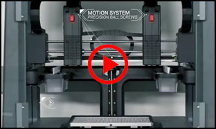 |
| See the video of Metal 3D Printing |
|
|
New technology in metal 3D printing has contributed to a desktop metal 3D printer as well as companion production version being offered by an American company called Desktop Metal. Up until now, expensive direct metal laser sintering technology has been used for 3D metal printing. While Desktop Metal’s desktop printer cost is nowhere near desktop plastic 3D printers, it has brought costs down substantially and made desktop metal 3D printing a reality. BMW, GE, Google, Lowe’s and others have made investments in this company. |
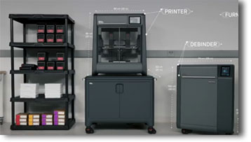
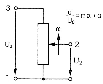 Figure 1
|
Linearity Independant and absolute linearity terms express the extent to which the voltage output, from a position sensor or potentiometer, and also other types of angular of linear movement sensor, differs from a theoretical function similar to y = (m • x) + a. Where “m” represents gradient and “a” represents an offset. In the vast majority of cases, the desired output function is directly proportional to the angle or linear movement that is input. In the example shown in figure 1, m represents the gradient (sometimes called gain), a is the offset voltage of the potentiometer and α is the linear or angular travel. U0 is the input voltage and U2 is the voltage across the wiper and ground. Where there is an absolute linear relationship, deviation is referred to as linearity. An index point on the actual output is required. The opposite wording use is the case for independent linearity, as described below. |
|
|
|
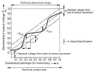 Figure 2 |
Independant Linearity If a voltage Uo is applied to a potentiometer with a linear characteristic as in Fig. 1 and the wiper is moved in direction a (standardized movement, angle 0:1 where 1 represents 100% - full scale angle or stroke) then the relationship illustrated in Fig. 2 will exist between the output voltage and the mechanically input value. The maximum deviation of the potentiometer curve from an ideal straight line is referred to as the independent linearity error. |
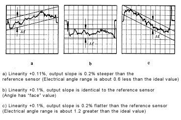 Figure 3 |
The slope and axis intercept of this straight line can be so chosen that the error f within the travel L1 is minimized. The error +/-f is indicated as a deviation in percentage terms of the output voltage from the theoretical in relation to the input voltage. Since direct measurement of the potentiometer characteristic does not make it possible to assess the extent of such an error, only the difference between the potentiometer characteristic and that of an essentially perfect master potentiometer is plotted as in the practical example given in Fig. 3. Today typical values for independent linearity lie between 0.2 % and 0.02 %. |

| Application: Automated Fire Engine Water Nozzle Positioning | |
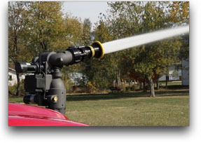 |
Water cannons are known as “monitors” in the trade and are used to put out fires using a powerful spray of water. Monitors are used by fire departments across the U.S. and for other applications. Accurately measuring the vertical and horizontal angles of the spray nozzle using Vert-X 1300 Series non-contact angle sensors allows users to automate and remote control their monitors so, for example, firefighters can keep a safe distance and handle more tasks on the scene. The Vert-X 1300 was selected for its precision, reliability, durability and ability to provide the correct position of the monitor nozzle even after a power failure. Resolution is up to 14-bit and repeatability is within 0.1%. |
| https://www.novotechnik.com/Novotechnik-Applications/automotivemobile.html |
|

|
If you have a question about position sensors for your specific application, Novotechnik engineers would be glad to speak with you. Contact us at Email Novotechnik [email protected] or call 800-667-7492. Please email suggestions for technical subjects you would like to suggest for this newsletter to this link: Newsletter Editor [email protected] |