
|
In this issue: Featured video: The Kitty Hawk Flyer To view newsletter in your browser click here. |
 |
| See the Kitty Hawk Flyer video |
|
|
Backed by Google founder Larry Page, Kitty Hawk is a company making personal flying aircraft. Their prototype was introduced this April and is called the Kitty Hawk Flyer. It’s an all-electric ultralight aircraft that was specifically designed to fly over water. The company states on their website that “you don’t need a pilot’s license and you’ll learn to fly it in minutes” and “it is classified under Part 103 of FAA regulations”. They also state that the “official Flyer will go on sale by the end of 2017.” |

| Introduction
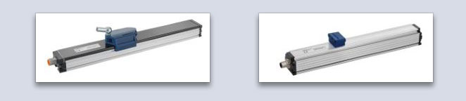
This paper discusses the basic setup and variants of touchless linear position sensors, the mechanical and electrical interfaces and some of the necessary considerations for a reliable installation on various types of machinery. We focus on magnetostrictive type sensors, however, the statements are valid for a variety of linear position measurement Non-contacting touchless linear position sensors based on the popular magnetostrictive or inductive principles allow for fast, precise and wear free electronic measurement of machine element position along a linear path. The sensor provides an electrical signal that is proportional to a mechanical position. Analog and digital interfaces are available. The electrical output signal can be used for display purposes or can be used for position feedback in closed control loops for all kinds of electric, pneumatic or hydraulic actuators. The sensors consist of two parts: the sensor housing forms the non-moving part, usually an elongated aluminum extrusion mounted to a machine or a stainless sensor rod with a sensor head for cylinder applications. The other part is called the position marker and is mounted to the moving part of a machine or e.g. to a piston in a hydraulic or pneumatic cylinder. The measurement principles are non-contacting, saying there are no sliding contacts involved like on potentiometers. The non-contacting sensors can also be touchless, meaning that there is no mechanical contact involved in the measurement setup consisting of the moving marker and the static housing.
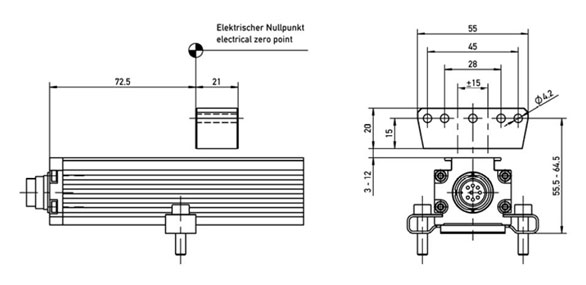
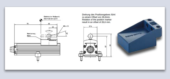
Mechanical Interface Extrusion type linear sensors are mounted to e.g. a machine bed or surface with a minimum of two and up to four metal clamps -dependent on total length of the sensor- for easy linear adjustments. The clamps should be placed evenly along the sensor housing, e.g. 1/3 of the total sensor length from both sides with 2 clamps and 1/4 with 3 clamps. The mounting bolts in the accessory pack usually come with a dry thread locker already applied. If not, the use of a liquid thread locker e.g. Loctite is recommended to secure the mounting bolts. The position markers come in two basic variants – a hovering version and a guided slider version. The hovering version is recommended in applications with a precise linear guide of the moving machine part. It is a mechanically wear free setup that will not be disturbed by an environment with dust, dirt and liquids around the sensor housing. However, this position marker needs to be mounted in a certain distance range from the sensor and with precise parallel alignment to maintain specified accuracy. With magnetostrictive linear sensors, the distance range between moving marker and static housing depends on the size of the position marker magnet. There are several sizes and shapes available providing coverage from 0.5 to 12 mm distance.
Modern inductive sensors with touchless markers have electronic circuitry and sending and receiving coils inside and no magnets. They typically work with a distance from 0.5 to 4 mm, and come in free-floating marker as well as guided configurations.
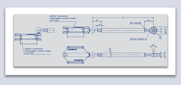
Linear movement applications with an off-axis pickup of the mechanical travel or movements that are not strictly linear due to mechanical play usually require a guided position marker. This marker comes with a low friction polymer on the guides which fit into the rails of the aluminum sensor housing and thereby form a precision slide bearing providing the parallel guidance to the sensor housing. This type of sensor is still a non-contacting, but not a touchless, as the guides are in touch with the housing rails. The marker slides on the rails mostly from both ends of the sensor housing and does not require additional lubrication. A spherical rod end with a female thread connects to a threaded push-rod. Usually, a second spherical rod end is required on the other end of the push-rod to prevent bending stress of the push-rod.
Article continues online, click here to read more. |

|
Designing Dancer Arm Systems
|
|
If you have a question about position sensors for your specific application, Novotechnik engineers would be glad to speak with you. Contact us at Email Novotechnik [email protected] or call 800-667-7492. Please email suggestions for technical subjects you would like to suggest for this newsletter to this link: Newsletter Editor [email protected] |