|
In this issue: Featured video: Tyto Care To view newsletter in your browser click here. |
 |
|
Source: |
A clinician receives and reviews the data, then communicates their medical opinion or diagnosis with the patient or their parent as well as any actions to be taken such as a prescription for an ear infection. |
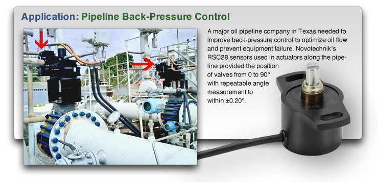
| Editor’s note: This tech tip is part 1 of a four-part series and covers why it is important to mount position sensors correctly and how to do it. The other three parts will be published in the next several Mechatronics Sense Newsletters. Part I - Contacting Rotary Sensors There are two parts of every shaft-type rotary (or angle) sensor that have to be mechanically attached to another part—the sensor body and its shaft. Sensor to mounting plate considerations Mounting the sensor body to a surface or mounting plate needs to be done properly to avoid potential damage to the sensor for plastic body sensors and/or erratic results if the sensor body is not affixed tightly enough. Damage to the sensor and inaccuracies can result if it is not mounted on a mounting plate that is perpendicular to the axis of the shaft. Other tips for mounting the sensor housing include the following: • The mounting plate can have through holes for mounting the sensor with nuts and bolts or, • it can have threaded holes for bolts without fastening nuts. While Novotechnik provides fitting bolts in metric dimensions, usually M4 x 0.7, if stainless steel or a different length is needed, the M4 bolt can be replaced with a #8 machine screw. • Mounting torque should be not exceeded, see your specific sensor specification. • Thread locker is highly recommended, e.g. Loctite 271. Sensor to drive shaft mounting considerations The drive shaft and the sensor shaft need to be exactly on the same axis when using a rigid coupling, otherwise radial forces might be introduced by means of redundant constraints which exceed specs and might wear the sensor bearing. Other tips for mounting the sensor drive shaft include the following: • The mounting screws are not designed to be used as precise locators.
 • Fork couplings come in versions with or without a spring, which eliminates all backlash. See image 3 below: 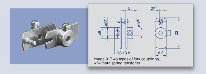 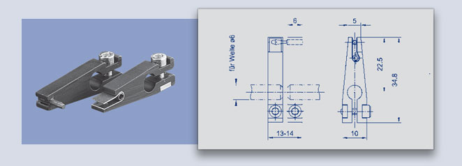 • These allow for quite a bit of radial misalignment ( e.g. 0.5 mm), however this misalignment will introduce a sinusoidal measurement error, which is easily approximated by the formula: α = arctan r/m, where α is the error angle in degrees, r equals the radius of the fork pin and m equals the misalignment of drive shaft to sensor shaft. • As an example, say the lower fork coupling has a radius of 22.5 mm. A misalignment of 0.1 mm creates an angular error of 0.25°, which equals an additional error of 0.01% using a 355° sensor. It is a good idea to design a system with a very small misalignment, if high precision measurements are required. • Last but not least, the mounting screws need to be fastened to full torque spec before the coupling set screws are tightened fully, to prevent axial bearing forces. |

|
Packing-Paper Machines
|
|
If If you have a question about position sensors for your specific application, Novotechnik engineers would be glad to speak with you. Contact us at Email Novotechnik [email protected] or call 800-667-7492. Please email suggestions for technical subjects you would like to suggest for this newsletter to this link: Newsletter Editor [email protected] |
