
| This issue’s articles: 3D Printing Breakthrough • Packaging machine dancer • Digital interface: SPI • Racecar steering control • Featured video: link to Rotary Sensors Video • To view newsletter in your browser click here. |
 Commercial Production Quality & Speedy 3D Printing
|
|
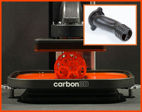
Breakthrough layerless 3D printing is emerging using CLIP technology to “grow” parts at 25 to 100 times faster speeds than currently available technology. CLIP stands for Continuous Liquid Interface Production and harnesses oxygen and UV light to selectively trigger or inhibit photopolymerization within the object being grown. Independent tests showed a complex object that took 3 to 11.5 hours using Polyjet, SLS or SLA 3D printing technology, was CLIP grown from a pool of resin in 6.5 minutes. Carbon 3D has a neat video of the object you see here being printed. Source: carbon3d.com. |
 Digital Interface Selection and Application
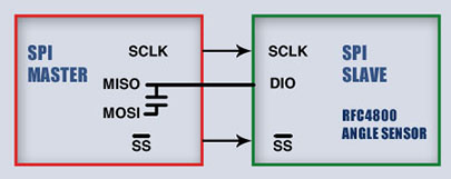
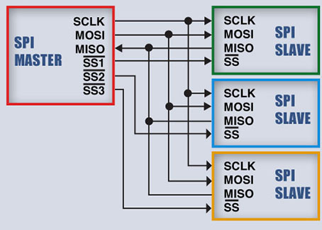
| Editor’s note: this section continues a multi-part series covering output interface selection and applications of the most frequently used interfaces. This issue focuses on reasons various digital options are selected and describes the Serial Peripheral Interface. The Serial Peripheral Interface (SPI) bus was developed by Motorola to provide synchronous serial communication between a master and several slave devices. The SPI bus is designed for high speed over short distances. The master is typically a microcontroller, and a slave can be any number of peripheral devices such as LED displays, SD cards, and sensors. Applications include agricultural equipment, medical devices and valve controls. SPI applications can be implemented in either a 3-wire or 4-wire configuration. Both configurations have a serial clock (SCLK) and slave select line. In the 3-wire configuration, the master has MOSI and MISO connections, but they both communicate with a slave over a single DIO (data in/out) line for half-duplex communication. With the 4-wire configuration both the master and slave have a MOSI (master out, slave in) and MISO (master in, slave out) line for full-duplex communication. Figure 1 below shows block diagrams for both 3- and 4-wire configurations. The master can communicate with one or many slave devices. There is a separate line for each slave, but the slaves can share SCLK, MOSI and MISO lines. Both Novotechnik and Contelec position sensors use a 3-wire configuration. Figure 1 SPI BLOCK DIAGRAMS SPI Bus Timing Refer to the sample timing diagram in Figure 2 below. When the master wants to communicate with a slave, it takes the line for the desired slave from a high to a low active state. The master then sends SCLK pulses to the slave, along with data. The slave also sends data to the master (either in full-duplex or half-duplex communication for the 4-wire and 3-wire systems, respectively). Figure 2 shows a configuration where SCLK polarity is inactive low, and the data bits are transferred in phase with the trailing edge of each clock pulse. This combination of SCLK polarity (CPOL = 0) and phasing (CPHA = 1) is referred to as SPI Mode 1. Other SPI Modes are determined by other combinations of CPOL (inactive low or high) and CPHA (data bits in phase with the leading or trailing edge of SCLK pulses). Both Novotechnik and Contelec position sensors follow SPI Mode 1. The communication that takes place between the master and a slave, from the time the master activates the to the time it deactivates the, is called a “frame”.
The SPI protocol is intentionally flexible in terms of the frame structure. In addition to the SPI mode, the device (slave) supplier must define the frame timing requirements (tn). This includes the pauses between /SS and the first SCLK pulse (t1), maximum SCLK frequency (t2), SCLK pauses between bytes (t3, t4), the pause between the last SCLK pulse and /SS deactivation (t5), the pause between /SS deactivation and data line high impedence (t6), and the minimum time to the next /SS activation to allow the slave to load new data to its shift register (t7). Other important considerations include data content (e.g. position value of a rotary angel sensor), number and size of data bytes, most significant bit (MSB) or least significant bit (LSB) first, and error-checking protocols (if any) that make up the frame. |


|
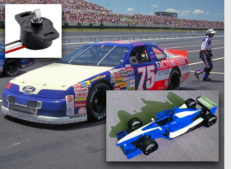
Automotive Racing
|
If you have a question. Contact us at http://www.novotechnik.com/salessupport.php.
Please email suggestions for technical subjects you would like to suggest for this newsletter to: [email protected]