
| This issue’s articles: New grippy material • Medical treatment machine • Digital interface: SSI • Malibu Boats’ wave control • Feature video: Malibu Boats Power Wedge II • To view newsletter as webpage select this link. |
 Incredible Grip Without Stick
|
|
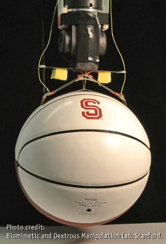
Stanford University engineering graduate students created a super grippy composite material (think geckos clinging to a wall) that “grips tightly to any textured surface, yet also releases without effort. They designed a gripping mechanism that can pick up objects of different shapes, sizes or textures – from trash bins to balloons to burritos – without having to squeeze them.” It even catches a thrown ball. According to Stanford News, "it's the first such system that doesn't rely on either a pressing force or a pulling force. The material achieves this by mimicking the tiny hairs on gecko toes." Applications include robotics, industrial and prosthetics. Source: stanford.edu. To view a video showing this gripping mechanism in action use search term: stanford grippy. |

 Digital Interface Selection and Application
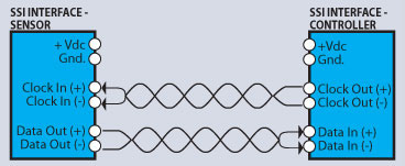
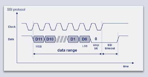
| Editor’s note: this section continues a multi-part series covering output interface selection and applications of the most frequently used interfaces. This issue focuses on reasons various digital options are selected and describes the Synchronous Serial Interface. The Synchronous Serial Interface (SSI) - a digital interface for absolute rotary and linear position systems. SSI incorporates serial transmission of data bits synchronized to a clock signal with a known start time. This is accomplished by using only 4 wires for transmission of data – two clock and two data lines – regardless of the number of bits of position information. The hardware used is based on the RS-422/485 standard. See the SSI Block Diagram below.  SSI is used in factory automation where cable lengths of up to 1,000 meters (~3,300 feet) may be used to reliably transmit the data from the machine axis being controlled to a controller. SSI control products are widely available at a low cost. A sensor with the SSI interface acts as a slave and responds to a request for position information from the master controller. A master (control device) sends a series of clock pulses to the sensor at a predetermined frequency called baud rate, like a modem. When the first clock pulse reaches the sensor, it saves the current position value in a register, and transmits that position as a digital bits - a succession of ones and zeros - with one position bit synchronized with each clock pulse. If the position value saved is 180° out of 360° full scale, the transmitted value would be (213)/2 = 4,096 for a 13-bit device. The position data is always transmitted with the MSB first, finishing with the LSB, then any additional information data (parity bits, fault bits, etc.) Each position and information bit is then stored in a register of the controller for further processing. See the SSI timing diagram below.
By varying tON and/or tOFF to change the Duty Cycle, the average voltage over time can be changed. These times are controlled by a moving rod (linear position sensor) or turning shaft (rotary position sensor) on an application to apply various position inputs to the position sensor. SSI Timing Diagram For SSI to execute correctly, baud rate, number of position/data bits, and the code format (binary or Gray code) must be decided and the same for both sensor and controller. The clock/data signals are transferred differentially via an RS-422 interface. Standard clock frequencies in the range of 60 kHz to 2 MHz can be achieved. Standard data formats include 13-bit and 25-bit data words. Other lengths of data words are often used, but in this case additional care is required to coordinate the sensor and controller capabilities. The maximum clock frequency is generally limited by the total cable length, and the drivers used.
SSI is a proven, reliable and cost-effective way to transmit digital position information over relatively long distances. Novotechnik offers a range of rotary sensors that implement the SSI interface. |

|
Malibu’s Making Waves
|
 Malibu Boats makes watersports boats that let boaters create customizable waves and wakes behind the boat for wakeboarding and wakesurfing. Controllable by a touchscreen control panel, Malibu’s control system moves control surface called Power Wedge II underwater to help get the boat on-plane and displace water to create waves and wake for wakeboarding.