| This issues articles: Graphene • Valve Control • Applying Analog Outputs • Motion Control of Treatment Chair • Feature video: Programming sensors for robotics • To view newsletter as webpage click here. |

|
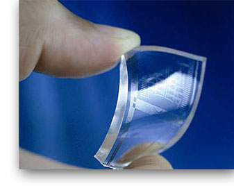
The Amazing Material Called Graphene Sources: www.graphene.manchester.ac.uk |
 |


| Editor's note: this section will be covering output interface selection and applications of the most frequently used interfaces in coming newsletters, starting with analog in this issue.
Analog interfaces are an obvious choice for design engineers needing to connect a position or angle sensor with a pre-selected control device that accepts standard current and/or voltage inputs. These sensors are generally available with one or more of three analog outputs: percentage of supply, defined voltage and defined current outputs. A voltage output option that is a percentage of supply voltage, say 10 to 90% of a 10 V supply would result in a sensor output range 1.0 to 9.0 V full range.
There are generally two defined current output ranges. These are 0 to 20 mA and 4 to 20 mA. These current values represent a minimum to maximum stroke range or angular range. Voltage output sensors are easy to implement as most PLCs have modules accepting a voltage input. Sensors with current outputs are used for longer cable runs and where electrical noise is Sensor current outputs of 4 to 20 mA have the additional benefit of making it possible to detect a broken or disconnected wire condition because the output would drop to 0 mA. Since this value is outside of the operating output range, it would indicate a fault condition. |

|
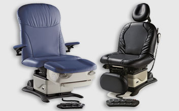
Medical Treatment Chair and Table Positioning |


 present in the environment, as current is inherently unaffected by noise and its level is sustainable over a long cable run with a sufficiently sized conductor wire gauge.
 To help the care giver provide the best treatment, healthcare providers often use a chair or table that optimally positions the patient. In medical practices many specialists need to perform procedures on patients to either help diagnose or treat a medical condition.