Novotechnik
CONTINUED...
Mounting Position Sensors Correctly
Note: It is necessary to mount the sensor and the magnet marker correctly centered on-axis to your application's rotating shaft, as well as perpendicular to the sensor and within a specified distance, again to the sensor, to obtain the measurement precision documented in the sensor data sheet.

T
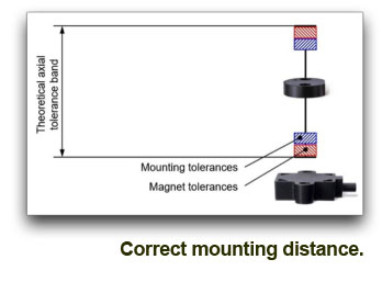
he Hall - Effect sensor chips require to be mounted on-axis with the rotating drive shaft of the machine. There are centering features included in the housings, that should be used as references to features on the mounting surface. These include the round circumference of the housing itself, locating pin holes or somewhat less precise-the mounting screw holes.

These sensors also need to be mounted perpendicular to the shaft referencing usually the top or the bottom of the sensor housing. Many sensors can nowadays be mounted on the top or bottom of their housing surfaces, allowing for measurements through non-magnetic walls mounting the sensor on the front, on a plate or a specially dimensioned hole in a mounting plate.

The correct distance range between magnet marker and sensor housing is specifed in the data sheets, however, as sensors can be combined with all kinds of sizes of magnet markers, it is important to follow the manufacturer's recommendation.

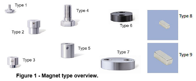
Selecting The Magnet

The distance range is defined by the strength of the individual magnet used. In general, bigger is better for a better linearity in spite of radial misalignment, but bigger magnets are more expensive.

The larger size of the magnet also allows for a larger maximum distance between sensor and magnet marker and with a stronger magnet the axial tolerance range increases as well. Magnet strength limits the usable distance range and permissible radial misalignment.

There are many ways to mechanically mount a magnet to a rotating part or shaft, and as a result there are many different types of magnet markers. Mounting methods include screwing a bolt onto the end of your application’s rotating part being measured, sliding a hollow shaft magnet over it, adhering with a permanent adhesive and fastening it using a coupling device.

The choice depends on the size, features like flats on the shaft and accessibility of the shaft end for setting the mounting screws. 6 mm, 8 mm, 10 mm and 1/8", 1⁄4" shaft sizes on the customer side are most common. With those, magnet markers with a hole on the back end are easy to mount with a set screw. (See figure 1, Types 2, 3 and 5). With larger shaft ends, holding the magnet marker with two screws can provide a cost effective mounting method (See figure 1 , Types 6 and 7).

The type of mounting also depends on how the angular index point is set during installation. If the angular adjustment is done with rotating the sensor itself or using a sensor with an electronic offset adjustment, simple threaded magnet markers are a safe option (Types 1 and 4). Custom solutions are feasible with aluminum magnet markers or – for larger quantities – with cost effective injection molded types. Customers can also choose from a variety of bare magnets (Types 8 and 9) with the correct field strength. They can be mounted on non-magnetic surfaces only.

Alignment
Touchless sensors specify a maximum misalignment distance from center-vertical to remain with specifications. With increasing radial misalignment ( due to mechanical play and/or mechanical tolerances ) the linearity error increases and the axial tolerance decreases, an example is shown in the next graph:


Final Remarks
Some of the sensors come with mounting hardware like clamps and screws, some do not. It is important to check for manufacturer's recommendations on screw size and screw mounting torque to prevent over torquing-or, conversely, a loosening mechanical connection - especially with some of the plastic housings. Screws might be metric, depending on the location of the manufacturer. Switching to english sizes if required is usually not an issue. Securing mounting hardware with a thread locker is always recommended. Mounting surfaces can be made of magnetic steel. However, when measuring through walls with the magnet marker on the other side, only non-magnetic wall materials will work.

When integrating a sensor into an application, cable routing needs attention as well. The direction of the cable exit is sometimes flexible, e.g. axial or radial, which helps to overcome dimensional restrictions in the application. Manufacturers also specify bending radiuses for their cables, partly for one-time or multiple bending operations. Sensors with individual wires will allow for smaller bending radiuses than cables, however, depending on the shielding requirements individual wires might not be an option. Cable clamps in 2 to 3 inch distance will prevent vibration and wear.